
The cylinder has a smooth exterior surface and there are no immediately apparent seams you might try prying at. There are regulatory markings printed in white on a black plastic surface; they’re legible. Run your finger around the rim… there’s not much to feel other than solid plastic.
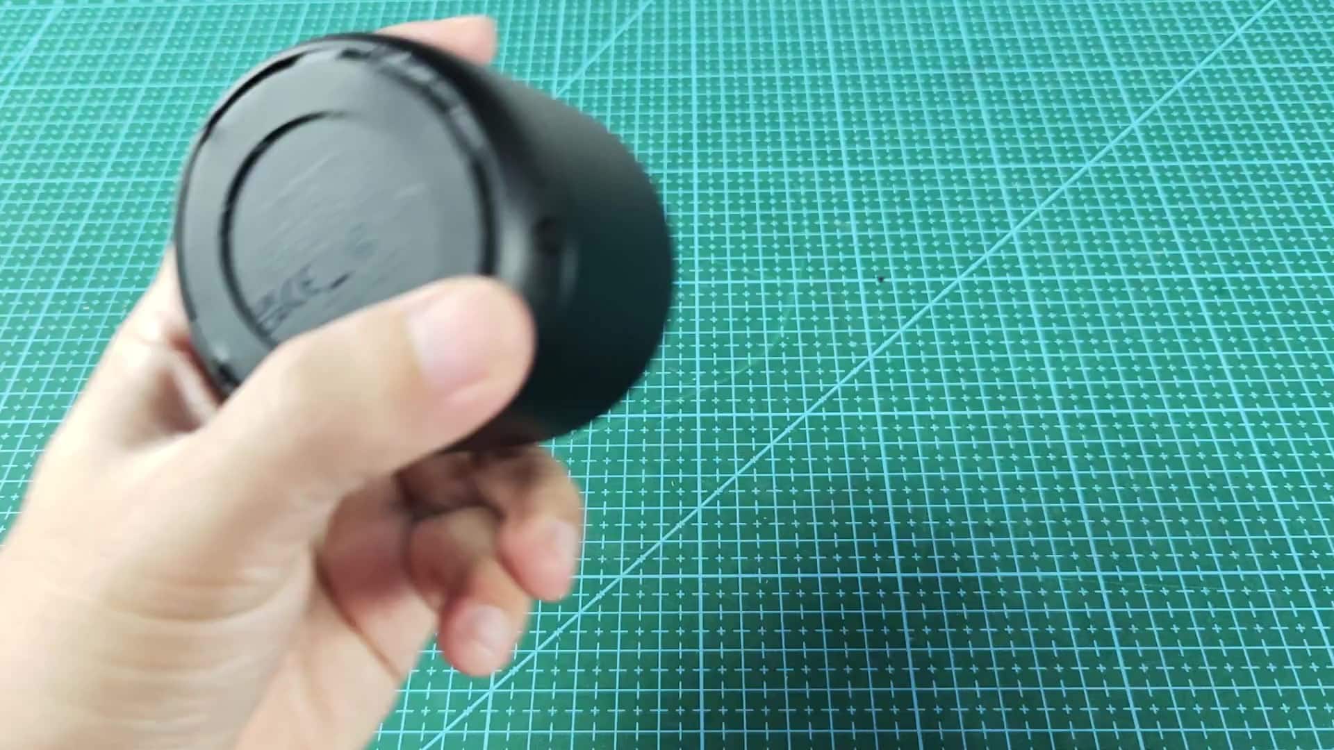
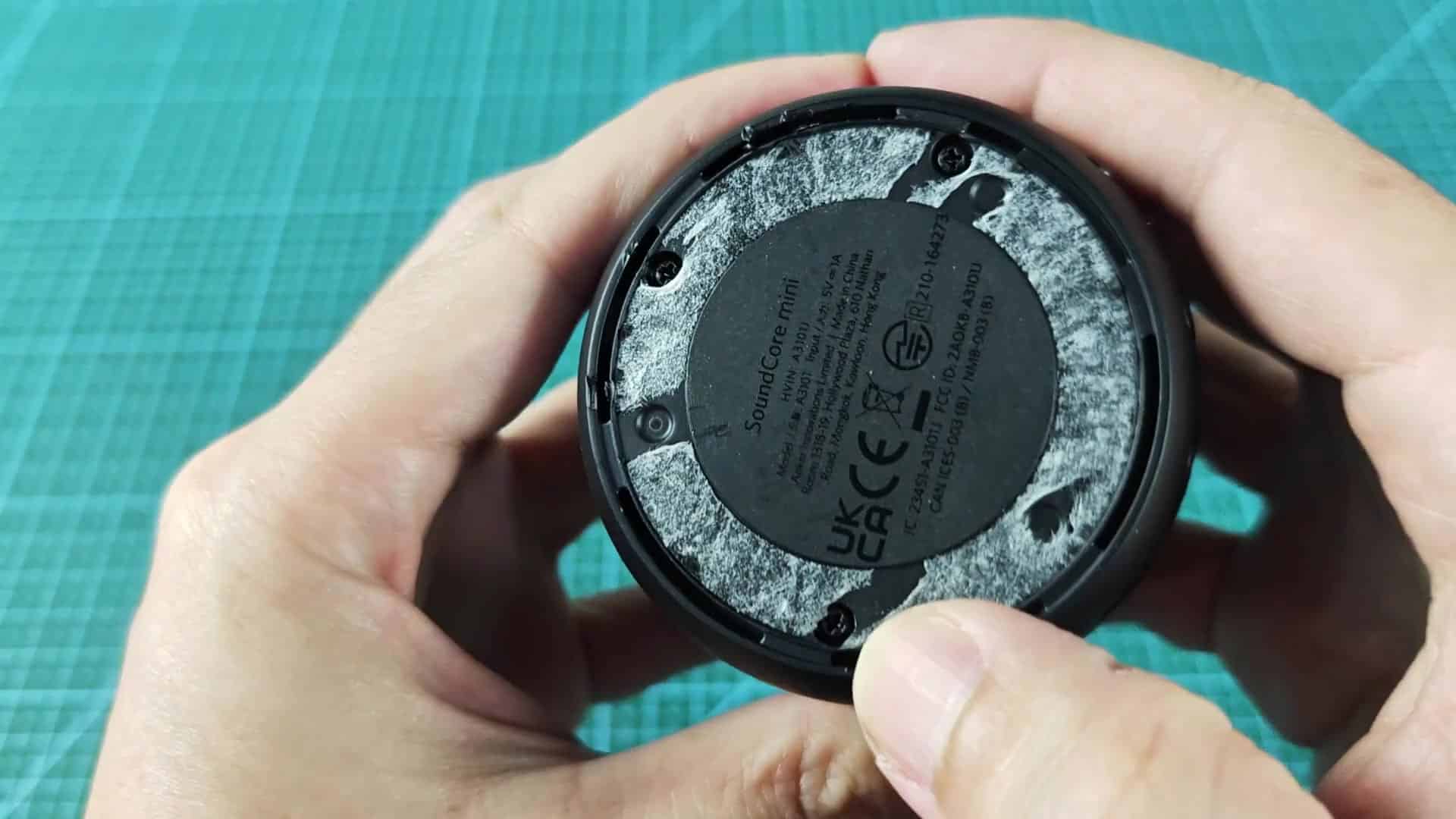
It seems totally stuck, enough to make you want to scream because it feels like you’ll have to use something sharp or hot to pop the lock. Pop the bottom cap off and the guts comes into view. There’s more inscribed text and logos, this time on base plate itself. The edges are riddled with tiny screw holes, this thing is held together by screws, and not merely glued.
Inspecting Internal Circuitry and Components
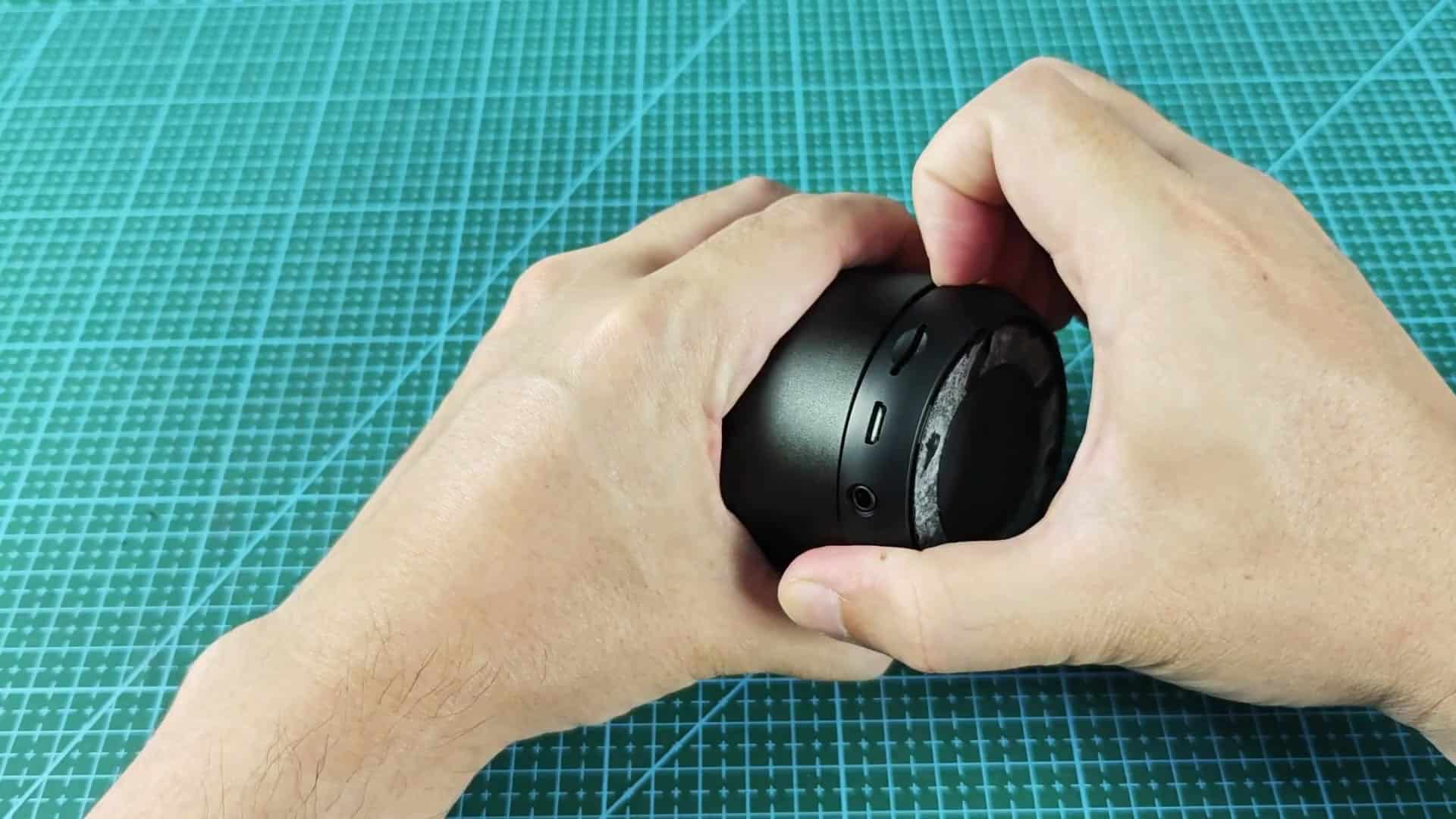
With even pressure, the two parts part ways like a clamshell, but there’s some resistance to get it started.
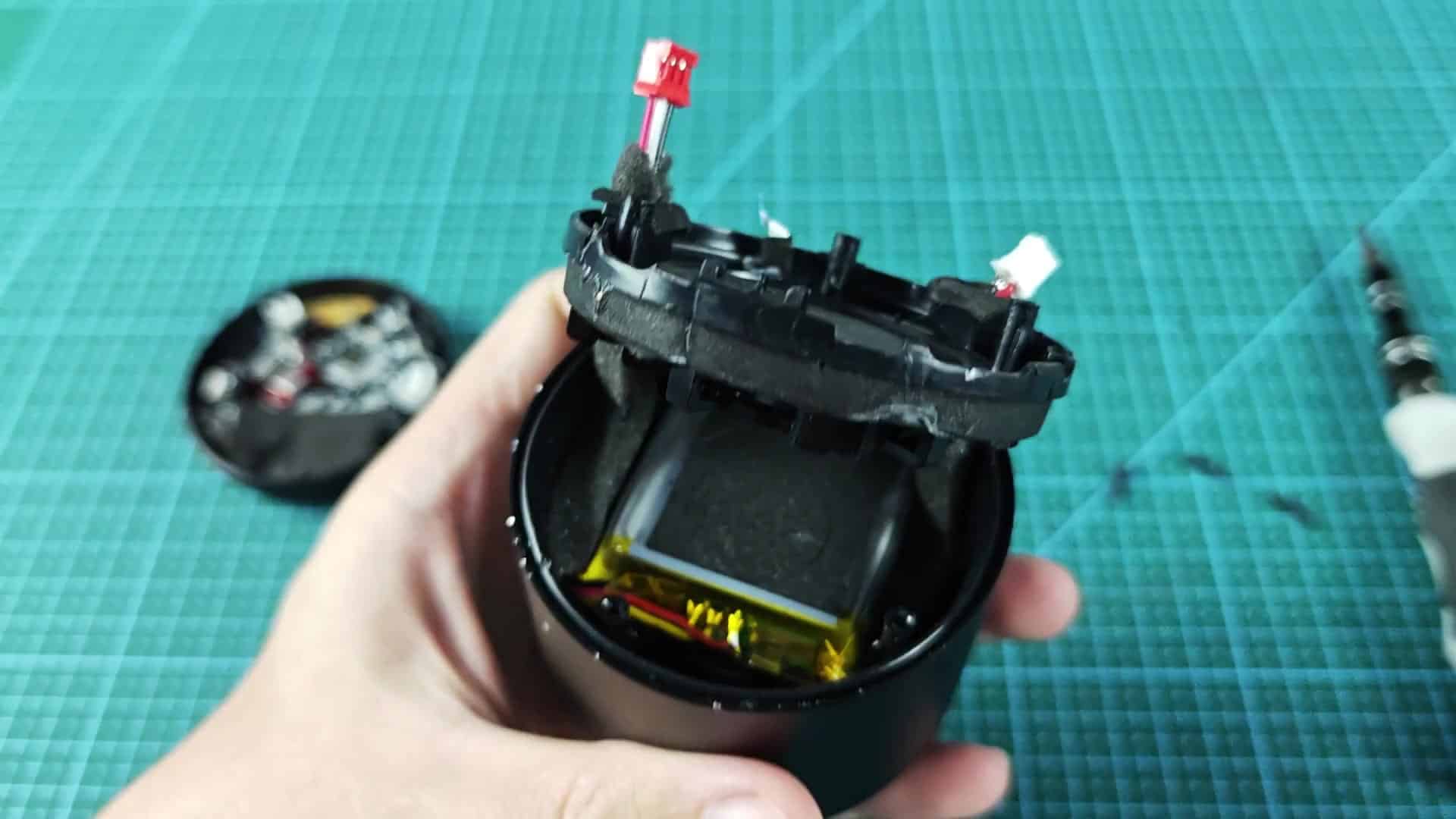
The first thing you notice is wiring that links top half to bottom. It’s a primary power or data link, a small red connector that stands out from the other dark components. No flapping cables about here; everything looks neat and built well, yet in a compact form.
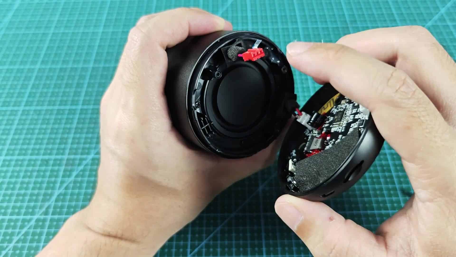
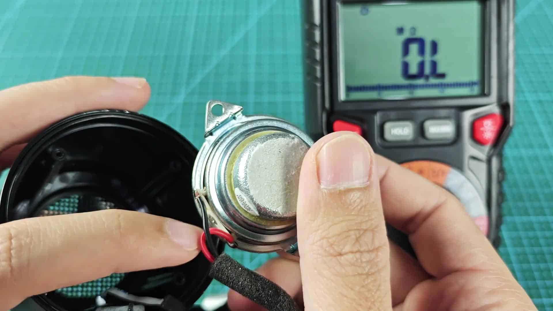
Inside the two halves we see some more: The speaker driver and a circuit board protected by foam padding. We also see the main circuit board and a speaker cone with a 4-ohm impedance rating; not surprising for such a compact portable Bluetooth speaker. It’s positioned to project sound well, and it all fits snuggly within the round body while using no wasted space.
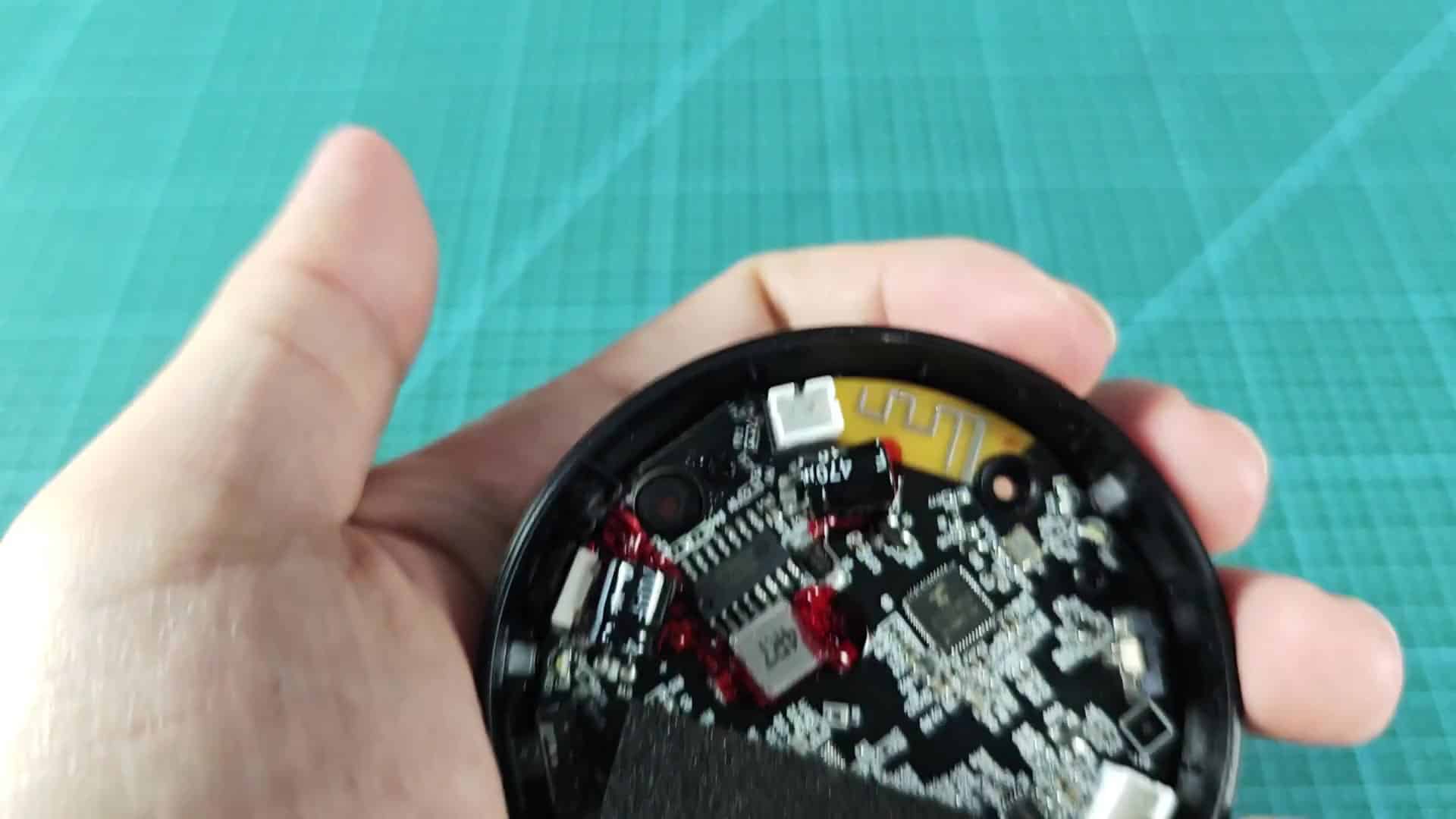
Removing the main PCB reveals a dense layout of electronic components. The green circuit board has visible printed traces, and near the edge there is a yellow region that looks like an antenna trace pattern. So much technology packed into this little round thing.
Be gentle with it; those traces can be very delicate and easily snapped off with one wrong move.
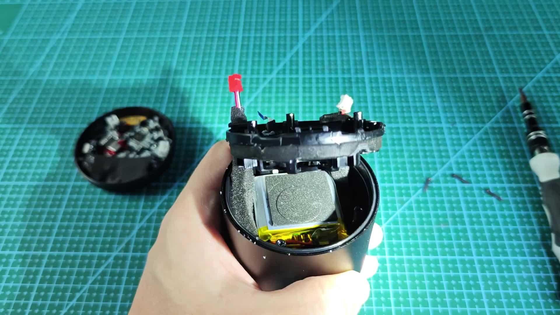
If you open it up more, the packaging inside reveals inner workings. There is a yellow piece of electrical tape covering the battery pack that’s sitting tight against middle of the housing. Wires connects from there to the main board.
You can’t even tell where the power is coming from just looking at the outside of it. That’s a sign of good design. Everything is tucked away out of sight.
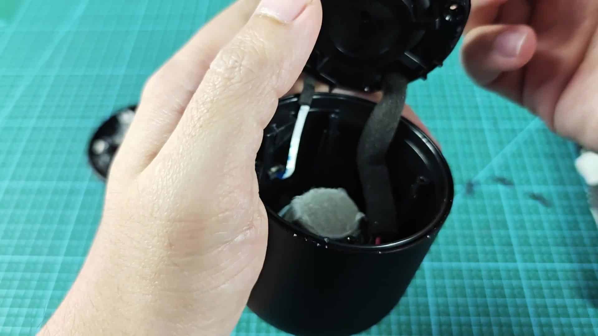
Here it is sitting down on a solid work surface. There’s room to take the rest of the screws out using that handy screwdriver lying there.
You can see where we got off on the red/white connector more clearly as you raise the top up more. Here you also get to see all of the rectangular battery pack which has been screwed secure into place so it doesn’t move when used. You need these kinds of devices to be very steady, and if necessary, you can just reseat them right then and there.
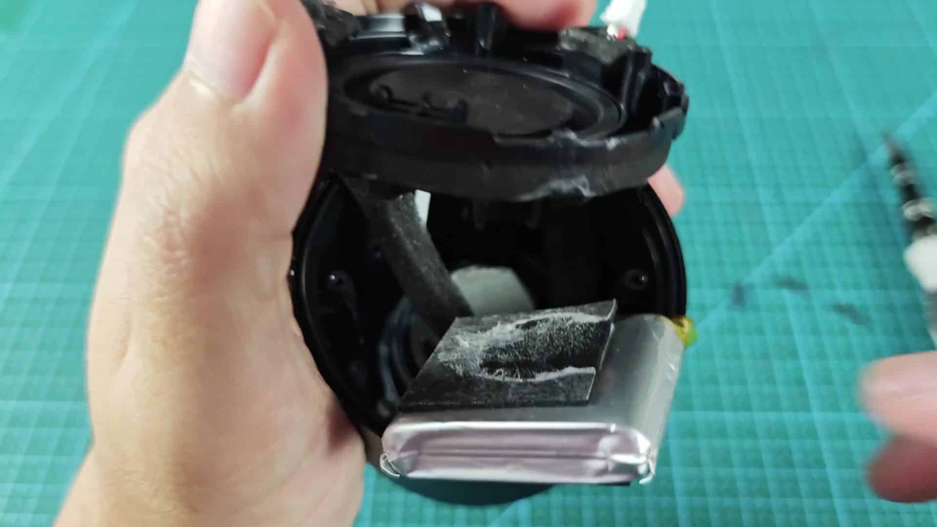
Getting it out involves gentle tugging in each direction. There’s a bit of resistance as the silver rectangular pack slides out. Yellow tape has been wrapped around the lower end to help with both grip and insulation.
Nothing shows up on the outside wrapping but it’s just that; nothing. It is a simple, workhorse power unit that you don’t want to damage when handling because of its terminals. Prioritize safety.
The battery has been removed and you’ll see the center cavity of the housing is visible. There’s a round piece of metal in the center of where the battery once was. It might be a mount for screws or adhesive. It also looks like part of the structure or a way to let heat escape.
The inclusion of metal in the otherwise plastic frame makes sense; it adds durability. It is smart engineering.
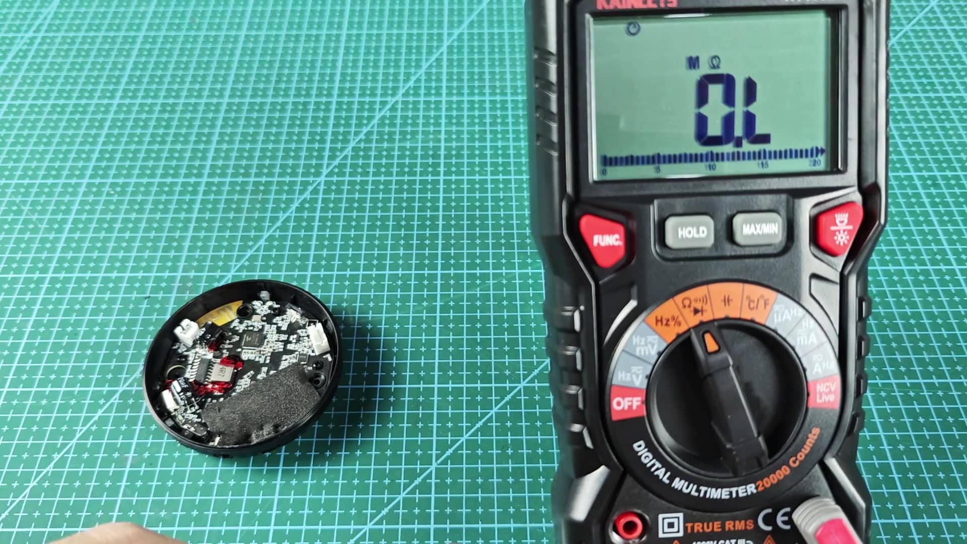
Before moving on, you can also verify the continuity of a few internal connections. A digital multimeter will do just fine here. When you touch the probes together, nothing is connected between them. You will see “OL” on your screen. That is infinite resistance, which means the circuit is open as it should of been.
Having one around while doing a teardown like this will give you true RMS readings for AC signals as well, so it’ll come in handy. For now, everything look good.
Change your meter to read resistance instead and get a closer reading. With the unit on mega-ohms the display will again say “OL”. This indicates the unit is not shorted and it is measuring the right component.
You need steady hands as you hold the little piece of metal next to the probes. If the resistance is high you know the components are well isolated from one another, this is what you’d expect to find in a healthy circuit. It seems funny, but it’s right.